When a chemical processing client approached Acuren with a recurring equipment failure, they had a seemingly simple hypothesis: the brackets were too weak. But through careful analysis and field measurements, Acuren’s engineering team uncovered a completely different root cause—leading to a cost-effective solution where the originally proposed “solution” would have made the problem worse.
The Challenge: Annual Forced Outages
A chemical processing vessel was experiencing a persistent and costly problem. This 8-foot diameter by 12-foot tall vertical vessel, used for batch processing of amine products, had an agitator shaft running through its center. At the bottom of the vessel, a steady bearing bracket secured the shaft. This critical component was failing repeatedly, with cracks forming at the bracket welds on a nearly annual basis.
Fig. 1 – Overview of vessel and lower head with boxed area highlighting the region of interest.
In multiple instances, through-wall cracking occurred, leading to forced shutdowns and emergency mobilization of a welding crew to perform repairs. This incurred repair costs and lost production opportunity costs. The client assumed that forces from the agitator, which rotated at 40 RPM, were simply too great for the bracket design. Their intuition suggested a straightforward solution: reinforce the bracket to make it stronger.
“The client wanted to follow the old engineering adage of ‘when in doubt, make it stout,'” explains Judah Rutledge, PE, Consulting Engineer with Acuren’s Austin office. “This approach makes perfect sense for components under external loads, but we needed to confirm if that was actually the problem.”
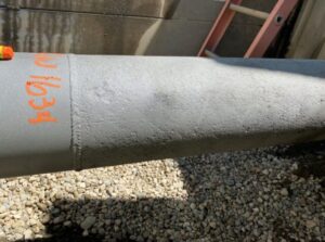
Fig. 2 – External surface of vessel head showing multiple weld repairs and visible deformation (arrow).
The Approach: Field Measurements Reveal the Truth
To properly diagnose the issue, Acuren’s engineering team decided to measure the actual stresses occurring during operation. This presented a significant challenge—the brackets were welded to the internal shell of the vessel, and confined space entry was not possible. Therefore, strain measurements had to be taken from the outside.
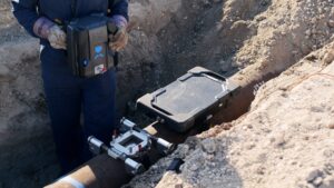
The team developed an innovative approach that combined engineering analysis with non-destructive testing. First, they created a finite element analysis (FEA) model to correlate internal bracket stresses to external strain. Then, they partnered with Acuren’s NDT team to precisely locate the bracket weld toe positions from outside the vessel using ultrasonic testing.
Fig. 3 – Strain gauge placement on vessel bottom head.
“We ended up working with a local Acuren NDT office and used ultrasonics to measure from the outside the exact location of the bracket on the inside so we could apply strain gauges at the correct location,” Rutledge said.
With this information, the team installed strain gauges on the vessel’s exterior directly beneath the internal bracket welds. They monitored the equipment through a complete production batch cycle, capturing real-time stress data from all operational modes.
The Revelation: Thermal Strain, Not Mechanical Loads
The data revealed a surprising finding: the agitator’s mechanical forces were contributing only a tiny fraction of the stress affecting the bracket. Instead, the primary driver was thermal strain from the vessel’s steam heating jacket.
“The fluctuating stress due to the agitator was very small compared to the stress due to thermal strain,” Rutledge explained. “While the agitator bearing moment generated a fluctuation of up to 11 microstrain, the thermal strain created up to 1,200 microstrain—two orders of magnitude greater.”
Fig. 4 – Temperature distribution (°F) showing high thermal gradients where heating coils surround the steady bearing.
Fig. 5 – Stress distribution (psi) showing yield-level stresses at the steady bearing bracket from heating coil strain.
When the vessel’s steam jacket activated, it created temperature gradients of approximately 200°F over just a few inches near the steady bearing bracket. This temperature difference caused expansion in the heated areas while adjacent regions remained cooler, creating severe thermal stresses that exceeded the material’s yield strength.
The strain gauge data directly correlated with the heating and cooling cycles of the vessel’s jacket, conclusively identifying thermal strain—not mechanical loads—as the root cause of the recurring failures.
The Solution: Reducing Thermal Gradients
Armed with this insight, the team ran Multiphysics simulations incorporating thermal and structural analyses to evaluate potential solutions. The results were counterintuitive: the client’s proposed “make it stronger” approach would have actually worsened the problem. FEA modeling showed that adding reinforcement would increase system stiffness, resisting the thermal displacement and significantly increasing stress.
Fig. 6 – Comparison between original design condition and added reinforcement pad, showing increased stress (psi).
“Understanding the physics driving the failure is critical to arriving at the proper resolution,” Rutledge emphasized. “If we had gone off of intuition and the proposed first cause, we would have made the problem worse.”
Instead, Acuren recommended removing the two steam coils nearest to the steady bearing bracket from service. This relatively minor modification would reduce the thermal gradient around the bracket while only marginally affecting process performance. Modeling showed this change would eliminate yielding in the bracket area and extend fatigue life by more than an order of magnitude.
Fig. 7 – Temperature distribution (°F) comparing original design (top) versus design with two coils removed (bottom).
Fig. 8 – Comparison of stress levels: original design (top) versus inactive coils near steady bearing (bottom) showing stress reduction (psi).
The Takeaway: Data-Driven Solutions Beat Intuition
This case study demonstrates how engineering intuition, while valuable, must be validated through measurement and analysis. The right solution wasn’t to strengthen the component against mechanical forces, but to address the thermal conditions creating excessive strain.
“Don’t implement a solution until you’ve fully defined and understood the problem,” Rutledge advises. “You have to understand what’s driving the damage before you can remediate it.”
The project also highlights the value of cross-functional collaboration between engineering and inspection teams. By combining NDT expertise with engineering analysis, Acuren delivered a solution that addressed the true root cause while working within the client’s operational constraints.
As Rutledge notes, “The holy grail of engineering analysis is when your measurement and your model give you the same answer. You can only have the confidence to predict the future once you’ve been able to effectively model the past that caused the damage in the first place.”
About Judah:
Judah D. Rutledge, P.E. is a Consulting Engineer specializing in Advanced Engineering/FEA at Acuren’s Austin office. With degrees in Mechanical Engineering from LeTourneau University, he specializes in fixed equipment inspection, repairs, alterations, and fitness-for-service assessments. Judah is passionate about solving solid mechanics problems real-time, whether it involves finite element models or hand-calcs on the back of a napkin.


